Do not use Heltec Meshtastic boards without a BMS
Wasn’t sure what to title this one because I actually noticed the issue playing with the common circuit that uses a P-MOSFET to disconnect the battery when a higher source voltage is detected, like here https://www.best-microcontroller-projects.com/tp4056-page2.html. I noticed that if you have some capacitance after the voltages are OR’d, and then you take away the higher voltage… well, now the P-MOSFET’s gate will open, but the capacitor will still be charged to a higher voltage than the battery. This will allow current to flow into the battery. In the circuit I was playing with, the capacitor could be freely charged from an 18V photovoltaic panel, so when the load presents high resistance, the voltage might climb to around 20V, much more than the 3S lithium cells … yikes. So instead for that circuit I’ve moved to fancier ‘ideal diode’ modules that are able to sense the higher capacitor voltage, not just the PV voltage.
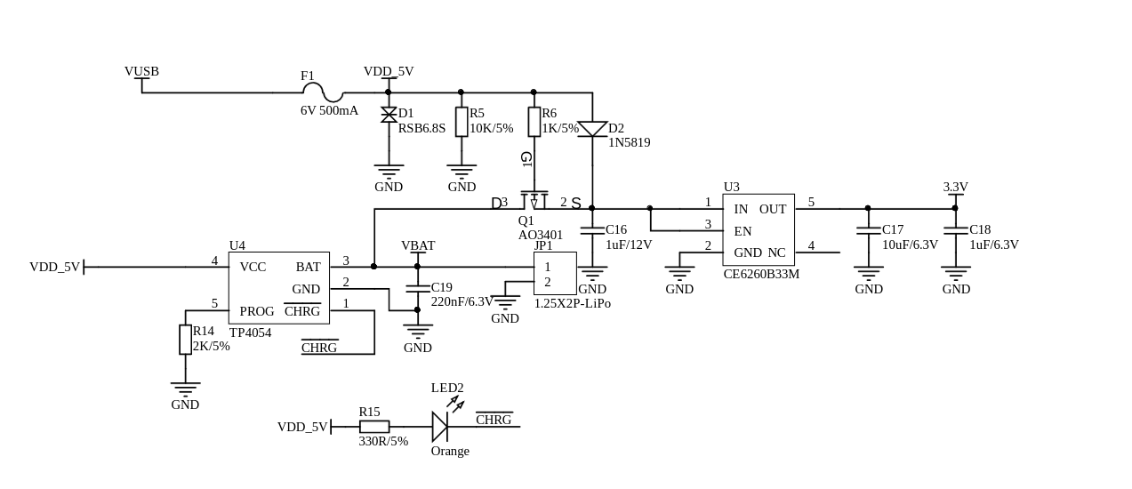
But that got me thinking where else this circuit crops up. And the answer is, basically everywhere. And led to the hopefully more useful title of this post. Here’s an excerpt from Heltec’s ESP32 LoRa v3.1 schematic from https://resource.heltec.cn/download/WiFi_LoRa_32_V3/HTIT-WB32LA(F)_V3.1_Schematic_Diagram.pdf
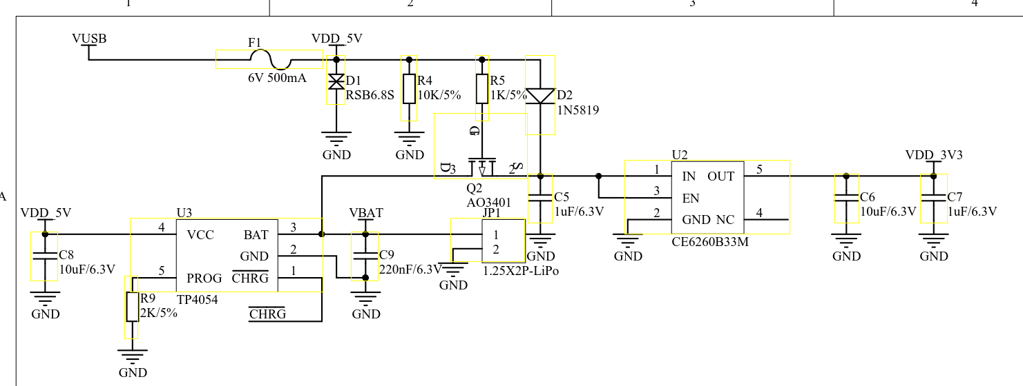
and here’s basically the same schematic in the Wireless Paper https://resource.heltec.cn/download/Wireless_Paper/Wireless_Paper_V0.4_Schematic_Diagram.pdf 
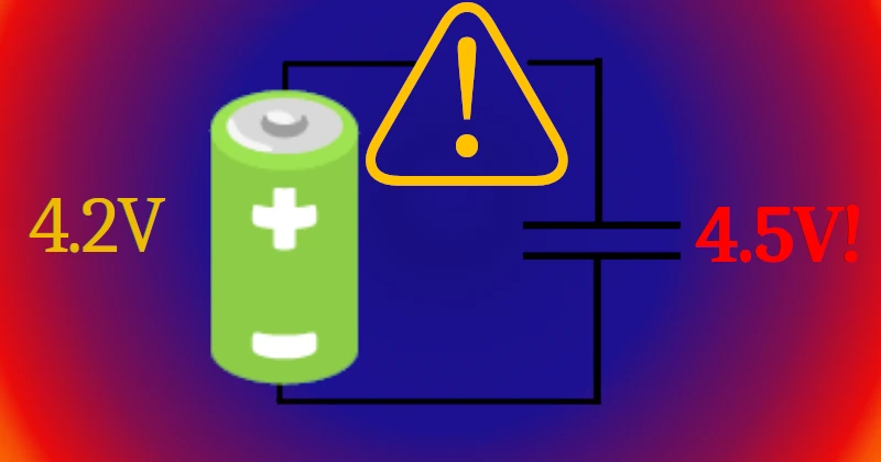
As you can see, capacitor C5 (C16 in Wireless Paper) is able to be charged up to Vusb minus the voltage drop of D2. The typical voltage drop of 1N5819 is 0.5V, so it could be sitting around 4.5V, which is higher than the 4.2V of a fully charged cell. TP4054 does not function as a battery protection IC, it only stops charging at 4.2V - so there’s nothing stopping the capacitor from trying to charge the battery, if the circuit doesn’t drain that voltage away. While it probably (probably) isn’t going to blow up in your hand from this, it’s really not good for the cell.
Update: Later consideration of the delay time tOC ~= 80ms in the DW01 and other things, I no longer think this helps. I’m not sure what the solution is. I don’t know how to make battery circuits unconditionally safe. But I don’t think the little bit of charge on a small capacitor is the problem anymore.
I recommend just adding a cheap 1S BMS module, the kind that has a DW01 and a couple of N-MOSFETs to disconnect the battery’s ground when overcharge (or overdischarge) is detected. Then the load will have to drain the capacitor below the DW01’s recovery voltage before the battery will be allowed to conduct again (or not? Maybe the cells will stay at 4.2V and refuse to conduct again until their self-discharge brings it below the release voltage). Speaking of overdischarge, there’s nothing preventing that here either, other than the dropout of the CE56260B33M regulator. I’m not sure what happens when this regulator hits its dropout voltage, so, that’s another reason to add a BMS.
Hope that helps someone. Feel free to ask questions, just wanted to write this quickly before moving on so I haven’t really explained as well as I maybe should.

