Repairing defective Baofeng microphone handset headphone output
Hello!
Been a while since I wrote a post, a bit demotivating when Google refuses to index your blog! A lot’s happened, but anyway, let’s get to it.
Today I received a cheap microphone handset intended for Baofeng HTs. The specific one I ordered is https://www.aliexpress.com/item/1005005591783043.html
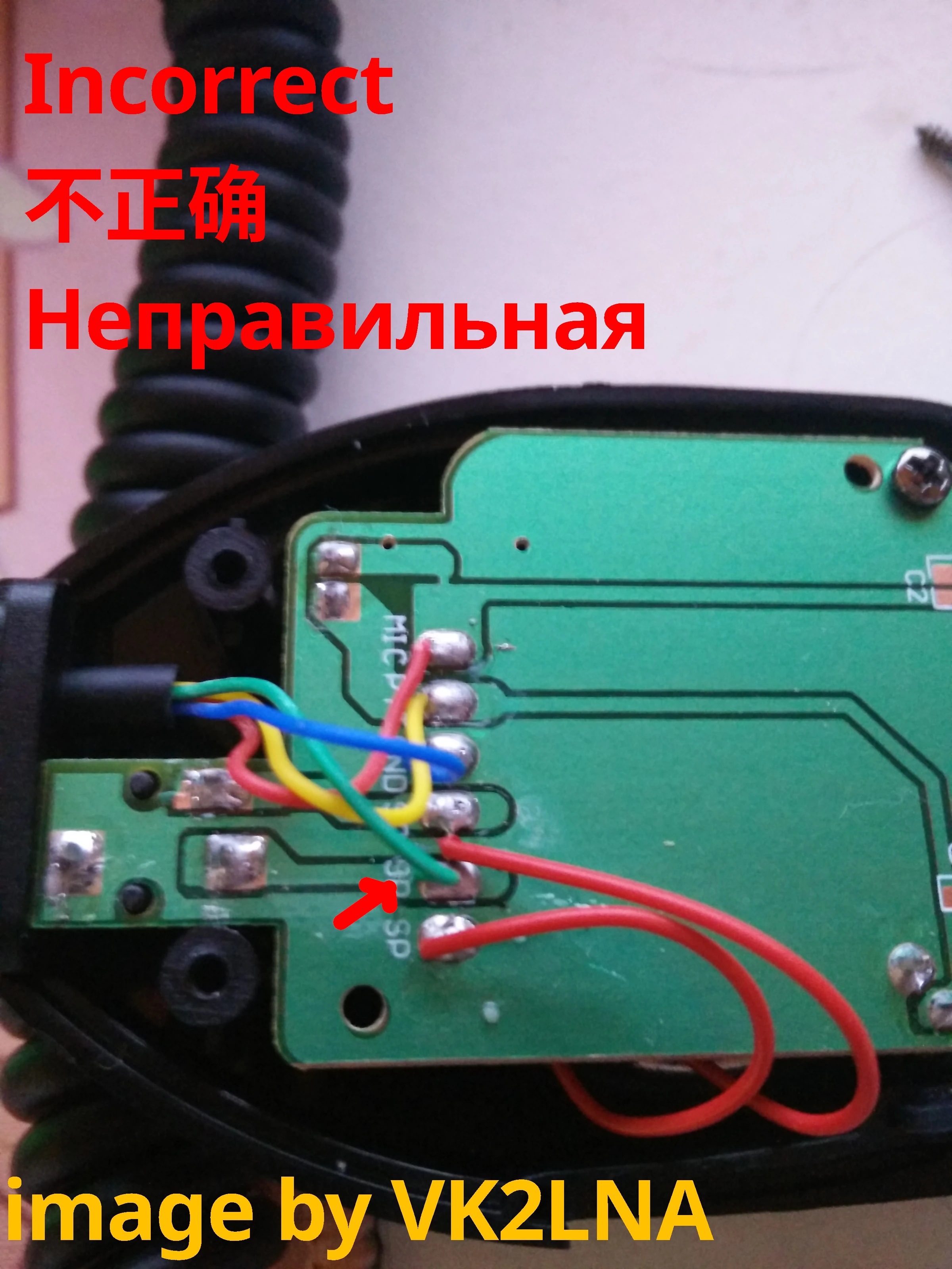
When I received it, it had an obvious rattle and the headphone output didn’t seem to work. When it rattled, I heard the rattling through one channel of my headphones. Hmm! Naturally, it was time to open it up. Here’s what I was presented with: 
Aha. So they run the speaker input from the radio to a normally-closed switch in the headphone jack, which then goes through the speaker to ground. Only… which pin have they connected the signal input and the speaker to? Yup… When you connect headphones, you’re not listening to the radio, you’re listening to the speaker!
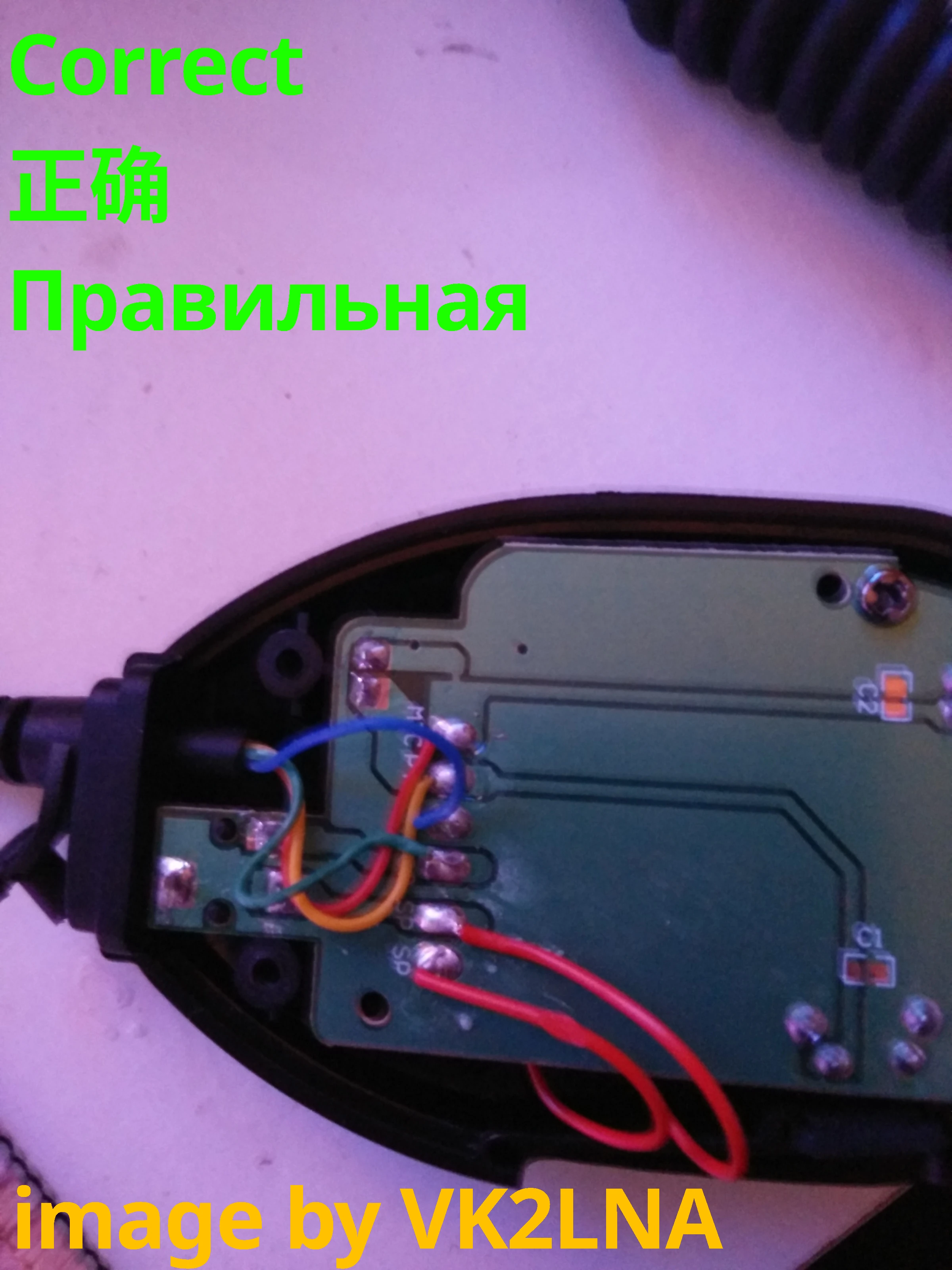
Luckily the fix is simple. Just swap the innermost red and green wires. Note that the colors may be different for yours. 
And the rattle? The speaker just wasn’t seated correctly in the housing. Unscrew the circuit board, push it in snugly, then screw the board back down.
And then you’re done! Headphone output should now work properly. Note that you’ll only get output on one (left) channel though - only the tip and sleeve are connected in the jack, not the ring. I consider it an advantage because I can wear only one ear and still hear ambient sounds while still getting great signal to noise with the ear listening to the radio.
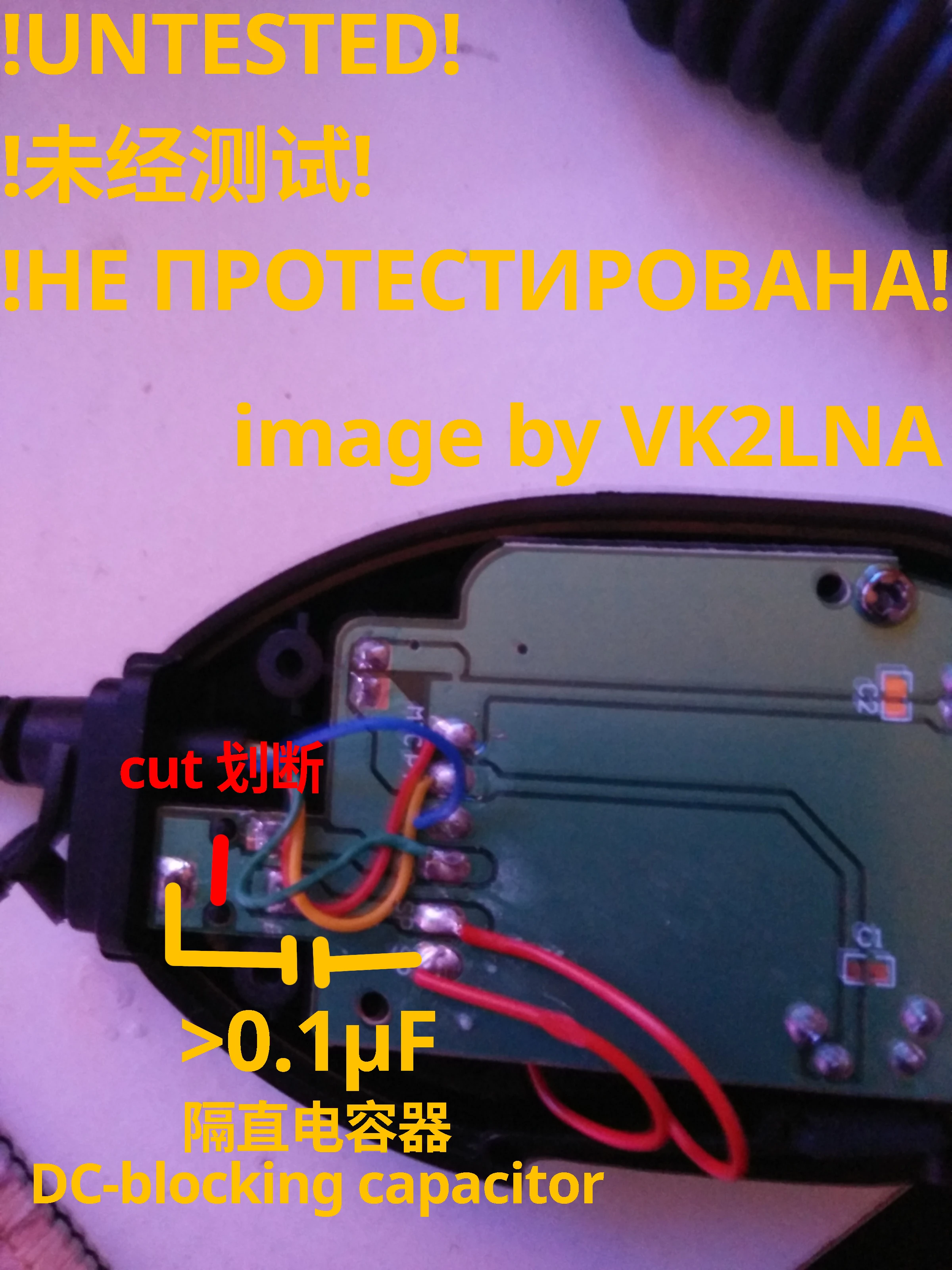
If your headphones have good bass response, you may be troubled by a loud click whenever your radio turns on its audio amplifier. This is likely due to a DC offset being presented suddenly to the headphones. I’m not 100% sure how best to deal with it but here’s a potential solution I haven’t tried yet that constructs a highpass filter on the headphone jack’s ground connection, without affecting how the internal speaker works.
- Cut the circuit board, along the red line, all the way through the copper trace to isolate the sleeve pin from ground.
- Ensure now that there is no conductivity between that pin and either the pin with the blue conductor, or the bottommost red speaker pin.
- Now, install a high value capacitor between the jack’s sleeve pin, and either the pin with the blue conductor, or the bottommost red speaker pin, as shown in yellow. Use an unpolarised capacitor because I’m not sure in which direction the DC bias goes.
BTW, don’t bother to populate the missing C1 or C2, those add filtering to the PTT line and mic input respectively, and won’t help for the speaker clicks.
Again, I have not tried this. If it works well, please let me know!
In general, please let me know if this page helped you out! You can either use the comment system below, or contact me as an amateur radio operator by whatever means you can.
Because the other thing that happened today, is I got my amateur radio callsign approved! I am now VK2LNA!
73 everyone, and good luck!

